The knowledge engine

OmniGram — the contradiction engine.

Omni — every domain, one graph. Gram — an engram: the physical trace a memory leaves behind. OmniGram is our engine's memory of how real systems get built: every engineering trade-off is stored as a contradiction — one property improving while another degrades — and the patterns that resolved it are recalled when a new design hits the same wall.

How it resolves

A trade-off is a coordinate, not a sentence.

Most knowledge bases store prose. OmniGram stores the shape of a problem: what improves, what degrades — and recalls how engineers have resolved that same tension before, across every field the engine has learned from.

↑ Improves
Signal strength — drive the sensing channel harder for better sensitivity
↓ Degrades
Thermal safety — the same drive heats the device past its safe limit
↻ The engine recalls how this class of tension was broken before — restructure the operation in time rather than fight it in one dimension — and the engineer re-derives the concrete solution for their own physics. The third example below shows one such resolution.
— · drag to orbit · ✦ symbolic illustration
Omni — every domain

Cross-domain recall

A thermal practice from one industry answers an enclosure problem in another; a sign-off discipline from chip design answers a firmware release gate. Principles cross domains — concrete recipes never do.

Gram — the engram

Memory with provenance

Every entry carries where it came from and how strongly it has been verified — so a recalled figure is never mistaken for one we measured ourselves, and a model result is never mistaken for a physical one.

Engine — resolution

Contradiction → pattern → design

Structure the trade-off, recall the patterns that resolved it, re-derive them for the target physics, verify with tools, and feed the verified result back in. The loop is what makes the memory grow.

— · drag to orbit · ✦ symbolic illustration

The engine

Seven steps from a document to a verified design.

Nothing here is a black box that answers questions. Each step takes something specific, does one thing to it, and hands on something you can inspect — which is why the last step can return provenance rather than only an answer.

  • unknown / raw input
  • process
  • contradiction
  • discovered relationship
  • resolved / verified

Input

Engineering knowledge arrives as documents, not as data. Papers, patents, schematics, netlists, models and specifications all describe the same physical world in incompatible notations, and none of them is indexed by the problem it actually solved.

  • literature
  • patents
  • CAD
  • RTL
  • SPICE
  • specifications
Enters
documents in six notations
Leaves
a corpus with no shared axis

Structure

Each source is reduced to the quantities it constrains and the relations between them. This is where the notation stops mattering: a paragraph in a paper and a line in a netlist can describe the same constraint, and after this step they are written the same way.

  • parameter extraction
  • constraint mapping
  • relationship graph
Enters
a corpus with no shared axis
Leaves
parameters, constraints and the edges between them

Contradiction

A trade-off is stored as a coordinate: the axis being improved and the axis that degrades when you improve it. Written this way, a tension found in one field can be compared with a tension found in another — which is impossible while both are still prose.

the axis you are pushing↑ improves
the axis that pays for it↓ degrades
Enters
parameters and their edges
Leaves
a coordinate, not a sentence

Recall

The same coordinate is looked up across every field the engine has read. What comes back is not a solution — it is the pattern by which that tension was broken elsewhere, carried with the source it came from. A mechanical answer and an electrical one can share a pattern and share nothing else.

  • pattern retrieval
  • cross-domain analogy
  • engineering memory
Enters
a coordinate
Leaves
candidate patterns, each with its source

Re-derive

A pattern is not a recipe, and copying a solution across domains is how you get a design that cannot work. The pattern is re-derived in the physics of the problem in front of you — its own equations, its own geometry, its own limits — producing a concrete design that is new even though the idea was not.

  • physics
  • mathematics
  • topology
  • geometry
Enters
candidate patterns
Leaves
a concrete design in this domain’s physics

Verify

The design is run back through the tools that can contradict it. A result that no tool has tried to break is a proposal, and it is labelled as one; the difference between a proposal and a verified design is the only distinction that matters at this step.

  • CAD
  • SPICE
  • FEA
  • RTL
  • simulation
  • physical test
Enters
a concrete design
Leaves
the same design, with a verdict attached

Return

What comes back is the design, the evidence behind it, and the trail from the original sources to the result — so the next engineer can check the reasoning rather than trust it. The resolved contradiction is written back, which is what makes the next problem of that shape cheaper than this one.

  • design
  • evidence
  • provenance
  • reusable memory
Enters
a design with a verdict
Leaves
design + evidence + provenance, and a memory that persists

Steps 03 and 04 are the ones that are hard to buy elsewhere. Everything before them is reading; everything after them is engineering. The middle is where a problem stops being yours alone.

One application

Example: automated design.

Engineering automation from chip to product is one application of the engine, not the engine itself. Three demonstrations where the contradiction loop visibly shaped hardware, followed by one concept project walked end to end. The three illustrations are symbolic; the walkthrough at the end shows real outputs of the process.

Open-source silicon flow
RTL to signed-off silicon

A microcontroller SoC on an open flow

An open-ISA processor core with on-chip memory and standard peripherals taken from architecture through register-transfer design, formal property proof, synthesis, physical design and multi-corner timing sign-off. The engine's contradiction discipline showed up as coverage closure: formal proofs generated the exact stimulus that simulation alone had missed.

formal properties proven timing closed across corners foundry precheck passed

⚙ tool-verified Design-flow results re-executed from source; no fabrication claimed. Illustration is symbolic.

Chip to board, closed loop
Sign-off, then the board

A sensor read-out chip and its evaluation board

A multi-channel analogue read-out chip closed sign-off — design rules clean, layout matching the schematic, pad frame merged exactly — and the loop continued past silicon: an evaluation board brings the finished chip out to sensor connectors, clock inputs and test points, fully routed with zero rule violations.

chip sign-off complete board fully routed, rules clean schematic-faithful pin map

⚙ tool-verified Chip verified by tool re-execution; board design-verified in CAD. Illustration is symbolic.

Simulation-driven mechanical design
Contradiction resolved by design

An acoustic sensing enclosure that stays cool

Sensitivity wanted more excitation power; the thermal budget forbade it. The engine's resolution pattern — restructure in time — became sequenced excitation: channels take turns instead of firing together, keeping the temperature rise small where simultaneous drive would have crossed the safety limit. The cavity, the assembly and every design gate closed inside the simulation loop before any material was cut.

contradiction resolved by design thermal-safe operating mode assembly verified in CAD

🔬 simulation-verified Simulation-driven design; physical validation is the named next step. Illustration is symbolic.

Concept to production

One concept, walked all the way to a product package.

A non-invasive saliva glucose screening aid, taken from a one-line idea to a complete deliverable set in a single automated run. Every stage below is a gate: a stage only hands over when its own checks pass, and a failure loops back to the stage that caused it instead of stopping the run. What is shown here is the process and its outputs; the internal design files stay with us.

  1. Requirements

    Customer needs mapped to measurable targets; risk analysis ranks what could go wrong before anything is drawn.

  2. Concept & prior art

    Sensing principle chosen against the literature and existing products; trade-offs recorded as contradictions.

  3. Circuit

    Schematic generated and electrically checked; the analogue front end simulated at every concentration it must read.

  4. Board

    Placement, routing and design-rule checks closed automatically; manufacturing files and bill of materials exported.

    output ① below
  5. Firmware

    Measurement state machine written and exercised against the same model the circuit was simulated with.

  6. Enclosure

    Housing generated from the board hand-off; wall thickness, fit and clearance verified in CAD, then rendered.

    output ② below
  7. Deliverables

    Catalogue sheet, user manual, feature sheet and a working demo assembled from the verified design in one pass.

    output ③ below
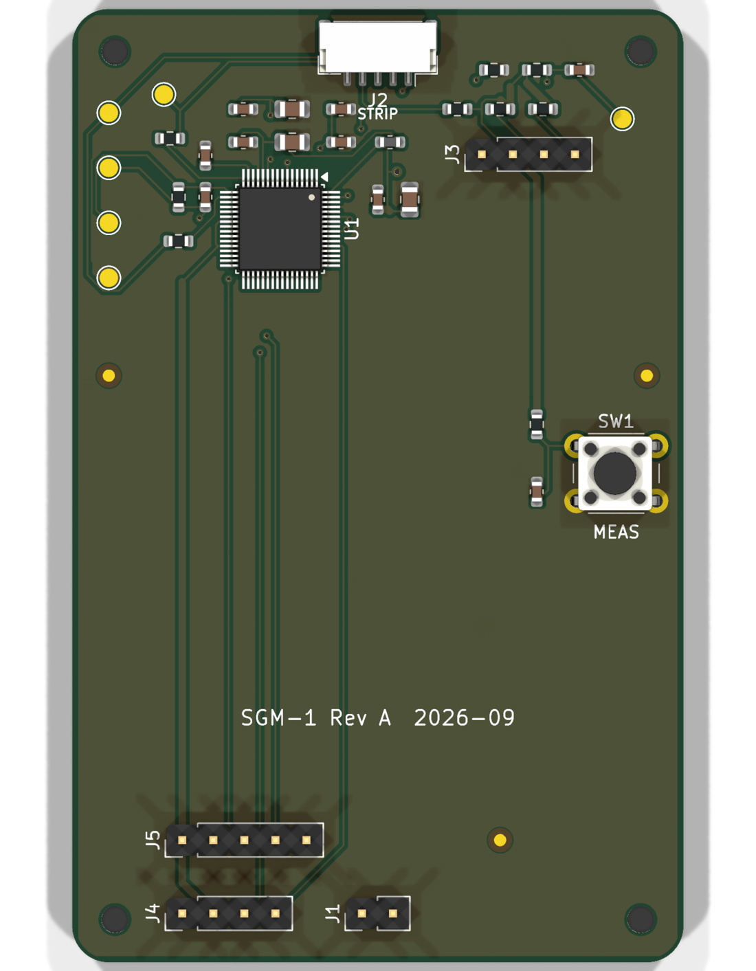
① Board · stage 4 Rendered top view of the two-layer measurement board: single-chip analogue front end, strip connector at the top edge, measure button, programming and sensor headers
Output ① · board render

The routed board, rendered from its own design files

Two layers, a single-chip analogue front end, a strip connector and one button. Placement and routing were closed by the pipeline with zero design-rule violations before this render was produced.

⚙ tool-verified Rendered directly from the CAD data; no board has been fabricated yet.

② Enclosure · stage 6
Output ② · working demo

Firmware and housing, shown working together

The enclosure came from the board hand-off; the screen sequence is the real firmware state machine, from strip insertion through the countdown to a result with its screening-only notice.

🔬 simulation-verified Rendered animation of the verified CAD model driven by the firmware logic. Not a physical unit; the displayed value is illustrative.

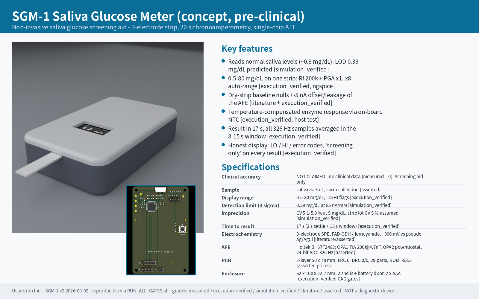
③ Deliverables · stage 7 Auto-generated one-page catalogue sheet: product render, key features and a specification table, each line labelled with its evidence grade
Output ③ · catalogue sheet

A catalogue page the pipeline wrote about itself

Features and specifications are pulled from the verified design, and every line carries the grade of evidence behind it. Where there is no data, the sheet says so rather than guessing.

🗣 design intent Concept, pre-clinical. Not a diagnostic device; no clinical accuracy is claimed anywhere in the package.

Evidence labels. Purple badges are tool-verified results re-executed from source; grey badges are design-verified items; amber would mark known-open items. The three case illustrations above are symbolic renderings, not the designs themselves. The concept-to-production walkthrough shows real outputs of the process for a pre-clinical concept; its source design files are not published.

Use the engine

Bring us your hardest trade-off.

Sensitivity vs speed, power vs precision, cost vs compliance — if it's a contradiction, the engine has a coordinate for it.